Description
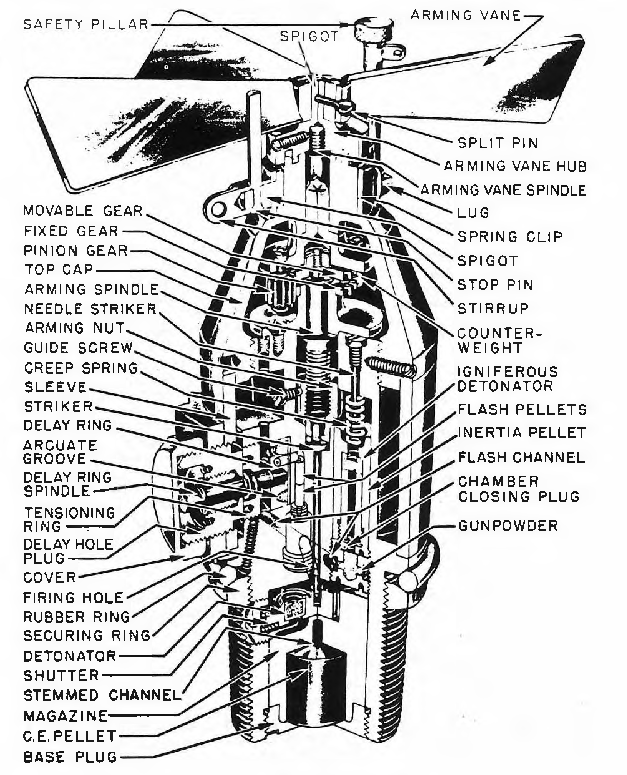
This fuze consists of a two-piece body, the upper part of which is aluminum, and the lower brass. The lower body is cylindrical, while the upper body is sloping. Through the upper body extend the vane hub and arming vanes, and on the sides are attachments for the safety pillar and the safety wire. On the lower body is found the delay ring with the markings ZERO. 0.5. 1.0. 1.5. 2.0, and BRIDGE. The delay setting spindle is covered by the setting-ring cap.
Within the upper body is housed the gear system, consisting of a movable and stationary gear. The former is attached to the end of the arming spindle and has 60 teeth, while the latter is fixed to a bearing in the fuze body and has 69 teeth. Around these move a rotatable pinion and counterweight. To the lower end of the arming spindle is threaded the arming nut. into which is fitted the upper end of the striker. The arming nut is prevented from rotating by a guide screw, moving in a longitudinal slot in the arming nut. In the unarmed condition the striker rests in a hole in the spring-loaded shutter, preventing it from moving into the armed position. When the gear system has moved the arming nut up and removed the striker from the detonator shutter, the shutter is forced over by its spring and locked in place by a spring loaded plunger.
Located to one side of the arming nut is an igniferous detonator, held off a needle striker by a creep spring. This detonator is carried in an inertia pellet, which contains a flash channel. The peHet is prevented from moving against the creep spring until after the arming nut is raised on the spindle. At the lower end of the flash channel in the inertia pellet are two chamber-closing plugs, one of which contains loose gunpowder. The plug containing this powder has radial holes extending from the powder cavity to an annular groove on the outside of the plug. A flash channel from the annular groove extends through the fuze body to a space between the delay ring and the tensioning ring. A hole housing the ignition pellet extends from the tensioning ring to the delay ring, which contains the circular groove holding the delay train. A flash hole pellet and two connecting hole pellets join the end of the delay train to the firing hole. The firing hole leads into a detonator located in the detonator shutter. Below this is a C.E. stemmed channel which leads into the magazine with its C.E. pellet. Around the threaded lower body of the fuze is a securing ring, above which a rubber ring is located to afford a watertight seal in the bomb.
Functioning
No information about functioning.
See Also
Nothing else to see.
Source(s)
OP 1665, British Explosive Ordnance (1946)
